Today, we were able to finish the entirety of the project. We were able to finish the prototype/project housing, envoy 2.0 but we also upgraded that to a Plexiglas/acrylic form of that prototype. Therefore, we came up with Envoy 2.1. We managed to laser cut all the parts to assembly successfully and the main assembly came out pretty sturdy. We added a switch mechanism to the main project set up that way we could switch it the LCD display on and off for presentation purposes as well as power-saving purposes.
The video below talks about Envoy 2.1 and the integrated circuit chip that was added to the main lab setup to blink the LED lights and give our project a cool dimension to it. The LEDs' also respond to the switch mechanism we added to the main project. Therefore, essentially, the switch controls two different tasks at the same time.
Also, for the ping sensors, we had to change from the lv-maxsonar-ez ultrasonic sensor (one sensor) to the parallax ping sensor (two sensors) because the lv-maxsonar stopped working. So because the parallax ping sensor is a two-headed ultrasonic sensor as opposed to the lv-maxsonar, we had to rebuild the back bumper of the envoy 2.1 prototype.
For the Design Lab Expo, we are going to refine envoy 1.0, which was the prototype design that we put on display for the Dean's challenge. Envoy 1.0 comprised of a cardboard house and acrylic locomotive. The design was able to put across the idea we were working on but not in the best way possible hence the need for an improvement. In our next prototype, Envoy 2.0, we are planning on putting together an assembly in solidworks to model a car and make some cuts and extrusions to make room for the LED display board and the ping sensor.
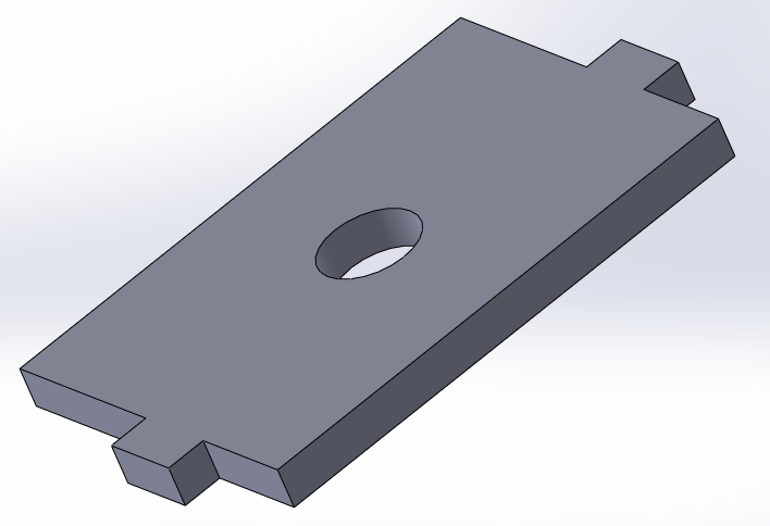
Today the group created a new design for the housing of our prototype. The following image shows the final assembly made in Solidworks of the updated design. The new design has a cutout for the ping sensor, LCD, and a switch to turn the electronics on or off which is positioned in the back of the prototype out of sight.
For today we managed to design a moving car of some sort using a pegboard, screws and bolts and 2 pairs of wheels. The setup for the main part of the functioning part of the project includes 2 breadboards, an arduino board and a display board. This setup will go on top of the peg board of the makeshift car and will then be covered by a box that we designed in solid-works.
The display board will be on the outside of the cover-box so that the car approaching can read off it. The ping sensor will have to be placed on the outside as well in order to lessen the interference in front of it.
Above the photos of the pegboard that we put together. As explained before, the main project setup will on top of the pegboard in top picture. The numerous holes in the pegboard will enable us to easily screw the cover-box over the set up.
The group managed to incorporate the accelerometer into the project. Now, when the code runs if there is a car in tailgating range of you while you're slowing down, the lcd display will display a message of "I'm slowing down" or "Braking." The group can have it flash repeatedly the closer a vehicle is to you in order to emphasize the message. The code for the group project is now as follows:
The group has begun working with the electronics portion of the project. The first task the group dealt with was displaying messages with an LCD display. This is shown in the following video and block of code.
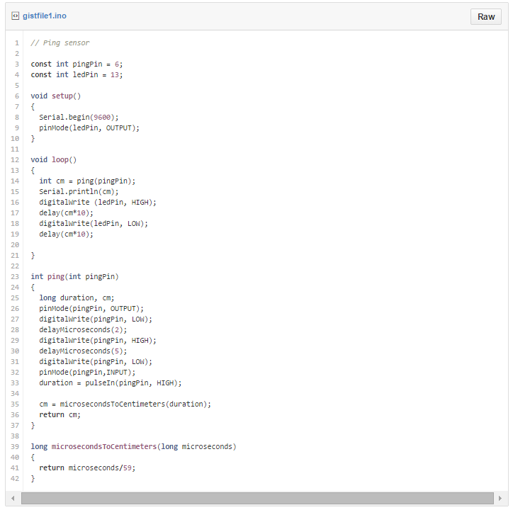
The next hurdle that the group faced was utilizing the Parallex Ping sensor to determine distances. The following video and code shows how the group got the ping sensor functioning properly.
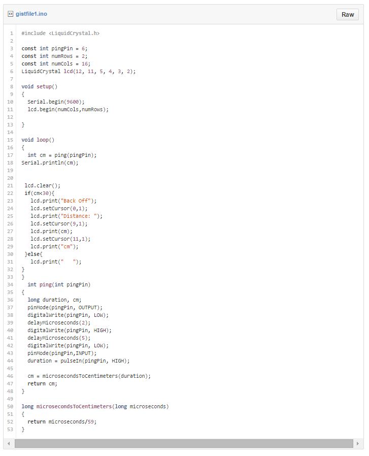
The last task of the day was to integrate the concepts of the both codes into one. The final result of this integration will display a message telling the object to "Back Off" as well as display the distance the object is from the sensor. The following video shows the circuit working as described and is accompanied by the code that allows it to function.
Team Accident Awareness is a mechanical design lab team that will utilize a sensor to detect approaching vehicles from the rear end of a car. The sensor will run using arduino and a message will be displayed by an LED display telling the tailgater to "Slow Down" or "Back Off".
The team members consist of Jeffrey Cheng, Kristofer Tite, Samuel Kibirige, Eric Carey from left to right
Day 1: The team met to discuss the electronics portions of the projects. The team discussed potentially building an FM transmitter from scratch. The video below served as inspiration and the team would build it using the same parts.
The parts needed for the sensor are as follows: 18AWG solid Copper Wire, 1/4-20 bolt, copper-clad board, liquid adhesive, two 0.01 micro-farad ceramic disk capacitor, 25K ohm resistor, electrolytic capacitor, 10k ohm resistor, transistor, two 10 pico-farad ceramic disk capacitors, 470 ohm resistor, battery and appropriate tools.
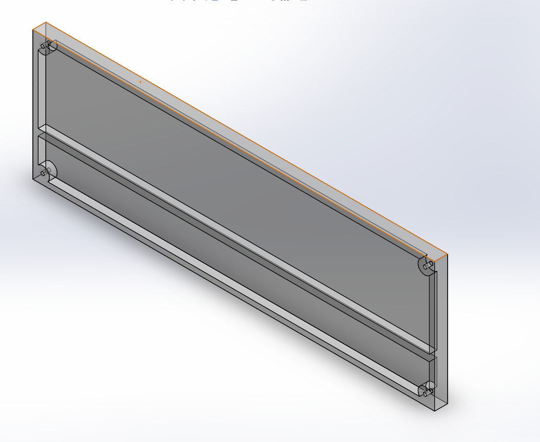
Other topics discussed were the code and housing, A solidworks render of a portion of the housing is displayed below. The housing would be created from a clear plastic like Plexiglass.